
The APA102 is an RGB LED in a small 5050 package that incorporates a microcontroller so you control the colour and brightness using a two-wire SPI signal. You can also daisy-chain a virtually unlimited number of them together, with individual control over the colour and brightness of each LED. Unlike the older NeoPixel LEDs, the APA102 will continue displaying the last colour and brightness you programmed, even without a signal.
You can buy them in strips, or as individual LEDs. I chose the individual LEDs, available from Adafruit:
or from Makersify in the UK:
https://makersify.com/products/adafruit-apa102-5050-rgb-led-w-integrated-driver-chip-10-pack-apa102c
You could carefully solder 6 wires to each 5050 package, but I mounted them on breakout boards available from Adafruit:
If you’re using an Arduino Uno or ATmega328 connect the pins as follows:
- Arduino Pin 11 to DI.
- Arduino pin 13 to CI.
- GND to GND.
- 5V to VCC.
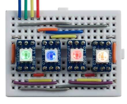
Here’s the circuit I used with four ARA102C devices:
The APA102 is programmed using a two-wire SPI signal (ignoring the enable signal). The data consists of:
- A start frame of 32 ‘0’ bits.
- A 32-bit frame for each LED, specifying the brightness and colour.
- An end frame of 32 ‘1’ bits.
The 32-bit frame for each LED consists of:
- Three ‘1’ bits.
- Five bits specifying the brightness, MSB first.
- Eight bits specifying the blue component, MSB first.
- Eight bits specifying the green component, MSB first.
- Eight bits specifying the red component, MSB first.
Because you can specify the brightness independently of the individual R, G, and B components, the overall resolution is actually 13 bits.
Here’s the definition of a uLisp program dis to control a chain of LEDs:
(defun dis (lst)
  (with-spi (str 10)
       (dotimes (x 4) (write-byte #x00 str))
       (mapc
        (lambda (col)
          (write-byte (logior (first col) #xE0) str)
          (mapc
           (lambda (b) (write-byte b str))
           (cdr col)))
        lst)
       (dotimes (x 4) (write-byte #xFF str))))
It specifies the enable signal as pin 10, although this isn’t actually used.
To use it, call it with a list of the following values for each LED:
(brightness blue green red)
where brightness is a number from 0 to 31, and the other numbers are values from 0 to 255.
For example, to set a row of four LEDs to blue, green, red, orange, each with a brightness of 1/32, evaluate:
(dis '((1 255 0 0) (1 0 255 0) (1 0 0 255) (1 255 0 255)))