Hi David ,
I was so brave to do some testing and found this solution.
First you have to change 2 files , variant.cpp and variant.h
In linux they are under :
.arduino/packages/adafruit/hardware/samd/1.7.14/variants/grand_central_m4
In variant.h near the end of the file you find extern Uart Serial1;
Just add after this line:
extern Uart Serial2;
extern Uart Serial3;
extern Uart Serial4;
In variant.cpp at the end of the file, add this:
Uart Serial2( &SERCOM_SERIAL2, PIN_SERIAL2_RX, PIN_SERIAL2_TX, PAD_SERIAL2_RX, PAD_SERIAL2_TX ) ;

void SERCOM4_0_Handler()
{
  Serial2.IrqHandler();
}
void SERCOM4_1_Handler()
{
  Serial2.IrqHandler();
}
void SERCOM4_2_Handler()
{
  Serial2.IrqHandler();
}
void SERCOM4_3_Handler()
{
  Serial2.IrqHandler();
}


Uart Serial3( &SERCOM_SERIAL3, PIN_SERIAL3_RX, PIN_SERIAL3_TX, PAD_SERIAL3_RX, PAD_SERIAL3_TX ) ;

void SERCOM1_0_Handler()
{
  Serial3.IrqHandler();
}
void SERCOM1_1_Handler()
{
  Serial3.IrqHandler();
}
void SERCOM1_2_Handler()
{
  Serial3.IrqHandler();
}
void SERCOM1_3_Handler()
{
  Serial3.IrqHandler();
}

Uart Serial4( &SERCOM_SERIAL4, PIN_SERIAL4_RX, PIN_SERIAL4_TX, PAD_SERIAL4_RX, PAD_SERIAL4_TX ) ;

void SERCOM5_0_Handler()
{
  Serial4.IrqHandler();
}
void SERCOM5_1_Handler()
{
  Serial4.IrqHandler();
}
void SERCOM5_2_Handler()
{
  Serial4.IrqHandler();
}
void SERCOM5_3_Handler()
{
  Serial4.IrqHandler();
}
Save and exit both files.
Now you can compile ulisp without errors about serial ports.
As you can see you can have 4 extra serial ports, but because I didn’t want to change the ulisp program, there will be 3 extra ports, being uart1, 2, and 3.
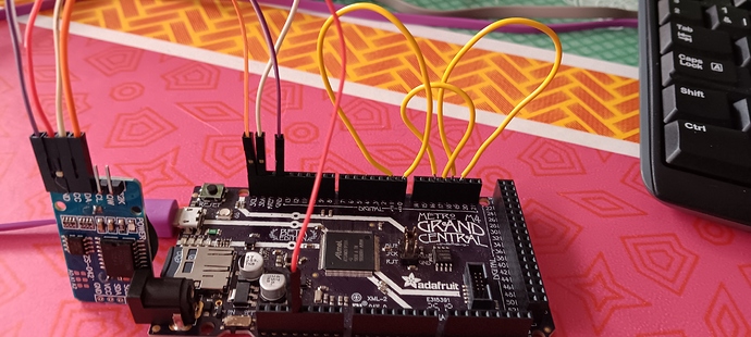
Because I wanted to be sure that other serial devices (being i2c and spi) kept on working , I wrote a small testprogram. For this you have to make a loopback on the 3 serial ports from tx to rx with a piece of wire. I will give the connections later on.
I also connected a RTC breakout board with a DS3231 real time clock on i2c port , and an sdcard . The testprogram writes a char to a serial port and reads it back. This char is being printed to the terminal. The char is 1 , 2 and 3 representing the number of the port. Then the sdcard is written to and read from and also printed on the terminal. At last the RTC is read and displayed on the terminal.
It all works fine !
Here’s the testprogram :
#|
***************************************
Functions to test all sercom devices
***************************************
|#

(defun pc (i) (princ (code-char (+ i (if (<= i 9) 48 55)))))

(defun pb (i) (pc (ash i -4)) (pc (logand i 15)))

(defun clock ()
  (let (hr min sec dow date mon yr)

    ;; Read the time from the RTC
    (with-i2c (str #x68)
      (write-byte 0 str)
      (restart-i2c str 7)
      (setq sec (read-byte str))
      (setq min (read-byte str))
      (setq hr (read-byte str))
      (setq dow (read-byte str))
      (setq date (read-byte str))
      (setq mon (read-byte str))
      (setq yr (read-byte str)))
    (pb hr)
    (princ ":")
    (pb min)
    (princ ":")
    (pb sec)
    (princ #\013)
    (pb date)
    (princ "/")
    (pb mon)
    (princ "/")
    (pb yr)
    (princ #\013)
    (princ #\013)
    (delay 250)))

(defun testsercom ()
  (loop
   (with-serial (str2 1 192)
     (princ "1" str2)
     (princ (code-char (read-byte str2)))
     (delay 50))

   (with-serial (str2 2 576)
     (princ "2" str2)
     (princ (code-char (read-byte str2)))
     (delay 50))

   (with-serial (str2 3 1152)
     (princ "3" str2)
     (princ (code-char (read-byte str2)))
     (delay 50))

   (with-sd-card (str "Greeting.txt" 2)
     (print "Hello" str))
   (delay 500)
   (with-sd-card (str "Greeting.txt")
     (print (read str)))
   (princ #\013)
   (delay 500)

   (clock)
   (princ #\013)))
The settings for the serial ports are : (numbers as printed on the pcb)
0 = RX serial1
1 = TX serial1
18=TX serial2 on sercom4
19=RX serial2
16=TX serial3 on sercom1
17=RX serial3
not used in ulisp but exist now :
14=TX serial4 on sercom5
15=RX serial4
Hoping this info is useful to other users,
Regards,
Ronny

