
Version 4.1 of uLisp adds a register function to allow you to read the values of peripheral registers, or write values to the registers. It allows you to control the peripherals in the processor from a Lisp program, or interactively experiment with the peripherals by giving commands at the uLisp prompt.
The register function is currently only supported on the AVR version of uLisp, but I intend to support it on all versions.
Example
To read the register at address #x3e give the command:
> (register #x3e)
0
To write a value to the same register give the value as the third parameter:
> (register #x3e 123)
123
You can now confirm the contents of the register with:
> (register #x3e)
123
uLisp provides predefined keywords for the port registers. For example, on the ATmega328P used on the Arduino Uno these are: :portb, :ddrb, :pinb, :portc, :ddrc, :pinc, :portd, :ddrd, and :pind.
For any other registers you want to access you will need to specify their address, or define a variable to refer to them. To find the addresses for each register see the Register Summary in the processor’s datasheet. For example in the ATmega328P Datasheet see Table 30, page 275.
The following examples are based on the Arduino Uno, but it should be easy to modify them for the other AVR processors.
Writing to the general purpose registers
The AVR processors include three general-purpose 8-bit registers, that you can write to and read from a program. On the ATmega328P, ATmega1284P, and ATmega2560 they are at the following addresses:
(defvar *gpior0* #x3e)
(defvar *gpior1* #x4a)
(defvar *gpior2* #x4b)
Blinking an LED
For the first example we will blink the built-in LED on the Arduino Uno board by directly accessing the port it’s connected to, without using the usual pinmode and digitalwrite functions.
We need to know that the LED is connected to the Arduino pin 13, which corresponds to bit 5 in port B. We can define a variable for this:
(defvar led #b00100000)
First we need to define it as an output by setting bit 5 in the data-direction register DDRB, without altering the other bits:
(register :ddrb (logior (register :ddrb) led))
To light the LED we set bit 5 in the register PORTB:
(register :portb (logior (register :portb) led))
Finally here’s the whole routine to flash the built-in LED, where the parameter specifies the bit in port B that the LED is on:
(defun blink ()
  (let ((led #b00100000))
    (register :ddrb (logior (register :ddrb) led))
    (loop
     (register :portb (logior (register :portb) led))
     (delay 1000)
     (register :portb (logand (register :portb) (lognot led)))
     (delay 1000))))
To run the program give the command:
(blink)
In fact the ports let you toggle bits directly by writing to the PIN register, so we can write the previous example more simply as:
(defun blink ()
  (let ((led #b00100000))
    (register :ddrb (logior (register :ddrb) led))
    (loop
     (register :pinb led)
     (delay 1000))))
Writing to I/O ports
The next example will show how to write characters to a seven-segment display connected to two I/O ports on the ATmega328P:
I built a prototype on a Sparkfun ProtoShield:
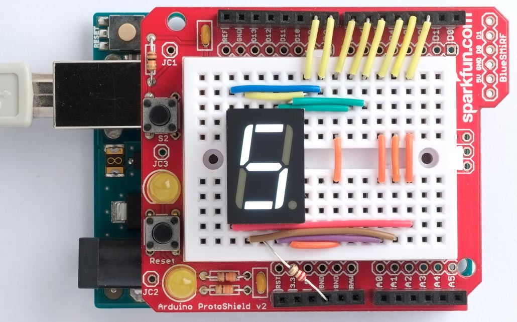
Unfortunately we can’t use all 8 bits of Port D, because PD0 and PD1 are used by the serial interface, so this example will use bits 0 and 1 of port B (Arduino pins 8 and 9) and bits 2 to 7 of port D (Arduino pins 2 to 7).
First we define the codes for the seven-segment hexadecimal digits:
(defvar seg '(#x7e #x30 #x6d #x79 #x33 #x5b #x5f #x70 #x7F
                   #x7b #x77 #x1f #x4e #x3d #x4f #x47 #x00))
Then here’s a routine to count up from 0 to F in hexadecimal:
(defun count ()
  (register :ddrd #xfc)
  (register :ddrb #x03)
  (dotimes (x 17)
    (register :portd (logand (nth x seg) #xfc))
    (register :portb (logand (nth x seg) #x03))
    (delay 1000)))
Controlling a timer
The next example programs a timer to flash an LED once a second.
The starting point for controlling the processor peripherals, such as the timer/counters, is to look at the datasheet for details of the addresses of the registers, and the function of each bit within the register. For example, for the Arduino Uno you’ll need the ATmega328P Datasheet.
The ATmega328P has three Timer/Counter peripherals. Timer/Counter0 is used for millis and Timer/Counter2 is used for note, so this example uses Timer/Counter1.
Timer/Counter1 can control the following I/O lines:
- OC1A - Arduino Pin 9 (PB1)
- OC1B - Arduino Pin 10 (PB2)
This example uses pin 10, which is bit 2 in port B. For this example you’ll need to connect an LED in series with a 220Ω resistor between pin 10 and GND:
The first step is to define this pin as an output:
(register :ddrb (logior (register :ddrb) #x00000100))
Defining the timer registers
The timer/counter’s registers are described in Section 15.11, page 108, in the ATmega328P Datasheet. For convenience we’ll define variables for the registers we’ll need:
(defvar *tccr1a* #x80)
(defvar *tccr1b* #x81)
(defvar *ocr1al* #x88)
(defvar *ocr1ah* #x89)
Table 15-5 Waveform Generation Mode Bit Description (page 109)
We want CTC mode, which counts up to the value programmed in the register OCR1A. This needs WGM13 to WGM10 to be set to ‘0100’. Two of these bits are in the register TCCR1A, and the other two in register TCCR1B.
TCCR1A – Timer/Counter1 Control Register A
We need to set COM1B1 and COM1B0 (bits 5 and 4) to ‘01’ to toggle the output pin when the counter matches the value we’ve set. We also need to set WGM11 and WGM10 (bits 1 and 0) in this register to ‘00’. This is achieved with:
(register *tccr1a* #b00010000)
TCCR1B – Timer/Counter1 Control Register B
We need to set WGM13 and WGM12 (bits 4 and 3) in this register to ‘01’. We also need to set CS12 to CS10 (bits 2 to 0) to ‘101’ to specify a prescaler that divides down the 16MHz clock frequency by 1024, giving 15625 Hz.
(register *tccr1b* #b00001101)
OCR1AH and OCR1AL – Output Compare Register 1A
To toggle the output every second we need to divide the prescaled clock by 15625. To do this we need to put the value 15624 into register OCR1A; it’s one less than the divisor we want because the counter counts from zero.
Since the register OCR1A is a 16-bit register we need to write the high byte first. Writing the low byte then copies across the full 16-bit value:
(defvar *divisor* 15624)
(register *ocr1ah* (ash *divisor* -8))
(register *ocr1al* (logand *divisor* #xff))
Here’s the whole sequence:
(defvar *tccr1a* #x80)
(defvar *tccr1b* #x81)
(defvar *ocr1al* #x88)
(defvar *ocr1ah* #x89)
(defvar *divisor* 15624)

(defun timer ()
  (register :ddrb (logior (register :ddrb) #b00000100))
  (register *tccr1a* #b00010000)
  (register *tccr1b* #b00001101)
  (register *ocr1ah* (ash *divisor* -8))
  (register *ocr1al* (logand *divisor* #xff)))
Once you execute (timer) the LED will continue flashing independently of what your Lisp program is doing, until you reset the processor.
The register function allows you to interactively experiment with the peripherals by giving commands at the uLisp prompt. For example, try the effect of changing the Timer/Counter1 prescaler to 256 as follows:
(register *tccr1b* #b00001100)