
In an earlier post I gave examples showing how the register function in the AVR version of uLisp allows you to control the microcontroller’s peripherals from a Lisp program, or interactively experiment with the peripherals by giving commands at the uLisp prompt.
This is a more complex example, showing how to write a reaction timer that uses the register function in conjunction with the ATmega328P timer/counter’s input capture feature to measure precise time intervals from a Lisp program.
Input capture
Input Capture is available with Timer/Counter1 on the ATmega328P and works as follows:
The 16-bit counter counts up from zero to its maximum value, #xFFFF, at a rate determined by the processor clock and a programmable prescaler. When an input is detected on the input capture input, the counter’s value is transferred to the input capture register. We can then read this to determine what time interval has elapsed.
An input capture flag tells you whether an input capture has happened, and an overflow flag tells you if the counter has reached its maximum value and wrapped around.
The following table shows the resolution and maximum time interval you can measure on the Arduino Uno with the different prescaler settings (based on its 16 MHz clock):
| Prescaler | Resolution | Range |
|---|---|---|
| 1 | 0.062 µs | 4.1 ms |
| 8 | 0.5 µs | 32.8 ms |
| 64 | 4 µs | 262 ms |
| 256 | 16 µs | 1.05 s |
| 1024 | 64 µs | 4.2 s |
When the counter overflows the maximum value an overflow flag is set, so you can actually achieve longer ranges by counting the number of times this happens before the capture occurs.
Reaction timer
As a simple example of using input capture here’s a reaction timer that measures your reaction time in responding to a light. I used an Arduino Uno, but it will work with any ATmega328P board.
You also could probably adapt it to other microcontrollers with a timer/counter that features input capture.
It will use the following pins on the Arduino:
| Signal | I/O pin | Arduino pin |
|---|---|---|
| ICP1 | PB0 | 8 |
| OC1A | PB1 | 9 |
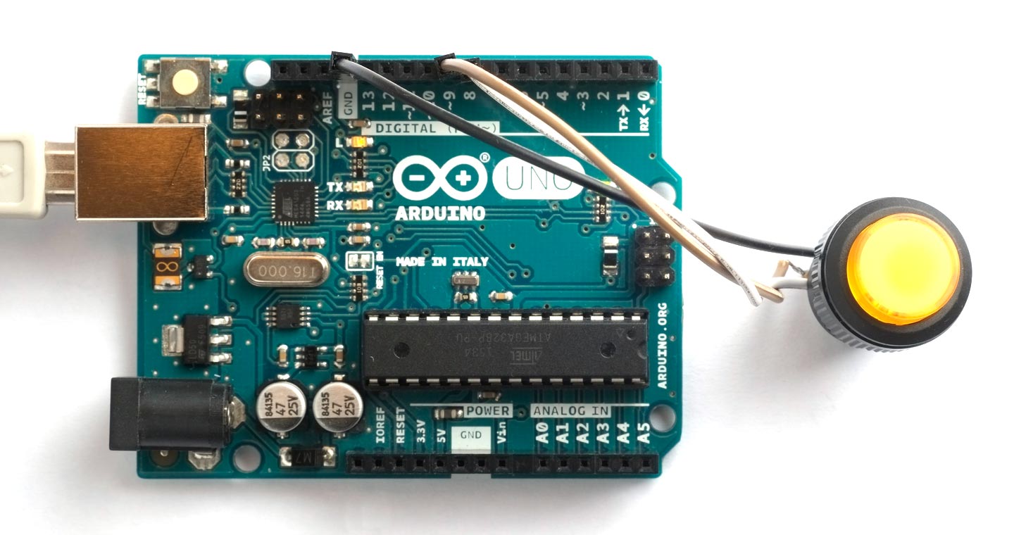
ICP1 is the input capture pin, and will be connected to a pushbutton. OC1A is one of the timer waveform outputs, and will be connected to an LED via a 220 Ω resistor:
I used an illuminated pushbutton, so the LED and button are integrated:
How it works
The program performs all the timing using the timer/counter peripheral which runs independently of the program execution, so the results won’t be affected by the response time of the uLisp program. The sequence is:
- The program clears the counter to zero, and then starts the timer/counter.
- When the count reaches #x0001 a compare match occurs which lights the LED.
- When the user presses the button, an input capture occurs which copies the current counter value to the input capture register.
- The program periodically checks the input capture and overflow flags and waits until one of them is set.
- If the input capture flag is set, the program reads the count in the input capture register.
- If the overflow flag is set, the counter has overflowed its maximum value and the user was too slow.
Timer/Counter1 registers
uLisp provides predefined keywords for the port registers. For example, on the ATmega328P used on the Arduino Uno these are: :portb, :ddrb, :pinb, :portc, :ddrc, :pinc, :portd, :ddrd, and :pind.
We will also need the following registers in Timer/Counter1. They are described in Section 16.11 Register Description starting on page 140 in the ATmega328P Datasheet, with the address of each register shown to the left of each register diagram.
| Register | Address | Description |
|---|---|---|
| TCCR1A | #x80 | Control register A |
| TCCR1B | #x81 | Control register B |
| TCCR1C | #x82 | Control register C |
| TCNT1 | #x84, #x85 | Counter - low byte, high byte |
| OCR1A | #x88, #x89 | Output compare register A - low byte, high byte |
| ICR1 | #x86, #x87 | Input capture register - low byte, high byte |
| TIFR1 | #x36 | Flag register |
Here are the Lisp statements to create variables corresponding to these registers:
(defvar *tccr1a* #x80)
(defvar *tccr1b* #x81)
(defvar *tccr1c* #x82)
(defvar *tcnt1* #x84)
(defvar *ocr1a* #x88)
(defvar *icr1* #x86)
(defvar *tifr1* #x36)
For the 16-bit registers such as TCNT1 I’ve only defined a variable for the low byte; to get the high byte use a statement such as:
(register (1+ *tcnt1*) 0)
The following sections describe each of the steps in the reaction timer program.
Setting up the input and output
We first need to set a pullup on the input pin, to hold it high when the button isn’t being pressed, and define the LED as an output. We could either do this with pinmode statements:
(pinmode 8 :input-pullup)
(pinmode 9 :output)
or by writing directly to the ports:
(register :ddrb  #b00000010) ; PB1 output
(register :portb #b00000001) ; PB0 pullup
Configuring the timer/counter
We want the timer/counter to be operating in Normal mode, which counts repeatedly from 0 to #xFFFF. This needs WGM13 to WGM10 to be set to ‘0000’. Two of these bits are in the register TCCR1A, and the other two in register TCCR1B.
In TCCR1A we need to set COM1A1 and COM1A0 (bits 7 and 6 to ‘11’) to take the output OC1A high at a compare match. We also need to set WGM11 and WGM10 (bits 1 and 0) in this register to ‘00’. This is achieved with:
(register *tccr1a* #b11000000)
In TCCR1B we need to set ICNC1 (bit 7) to ‘1’ to activate the input capture noise canceller, which requires four successive equal valued samples of the ICP1 pin for the capture to be registered. This ensures that when the user releases the button, contact bounce will not cause a second capture before we get a chance to read the first one.
In TCCR1B we also need to set ICES1 to ‘0’ to trigger capture on a falling edge on the input capture input, WGM13 and WGM12 (bits 4 and 3) to ‘00’, and CS12 to CS10 (bits 2 to 0) to ‘000’ to stop the counter:
(register *tccr1b* #b10000000)
Later, to start the counter, we will set CS12 to CS10 to ‘101’ to select a prescaler of 1024, giving a resolution of 64 µs per counter value.
Finally we need to set the compare value for the LED output OC1A to #0001, so the LED will light as soon as the counter starts counting:
(register (1+ *ocr1a*) 0)
(register *ocr1a* 1)
If you’re wondering why I don’t just turn the LED on from the uLisp program, the answer is that it would introduce an unpredictable delay between the start of the counting and the LED lighting; this way the delay is an exact 64 µs.
Measuring the reaction time
In preparation for the test we need to write a count value of zero into the counter. Since the register is a 16-bit register we need to write the high byte first. Writing the low byte then copies across the full 16-bit value:
(register (1+ *tcnt1*) 0)
(register *tcnt1* 0)
We also need to clear the input capture flag (bit 5) and the overflow flag (bit 0), by writing to the TIFR1 register:
(register *tifr1* #b00100001)
We then wait for a random time of between 5 and 9 seconds, and start the counter by setting the bottom three bits of TCCR1B to ‘101’. A compare match will light the LED, and the counter will start timing the user’s reaction time:
(dotimes (x (+ 5 (random 5))) (delay 1000))
(register *tccr1b* (logior (register *tccr1b*) #b101))
We then wait until the input capture or overflow flag gets set:
(loop
 (unless (zerop (logand (register *tifr1*) #b00100001)) (return)))
When a flag has been set we stop the counter and read the input capture register in the variable ic:
(register *tccr1b* #b10000000)
(setq ic (1- (logior (register *icr1*) (ash (register (1+ *icr1*)) 8))))
Because ICR1 is a 16-bit register, the low byte ICR1L must be read before the high byte, ICR1H. The 1- is to take account of the fact that the LED lights up when the counter reaches 1.
To turn the LED off ready for the next trial we reprogram TCCR1A to set the LED low on a compare, and force a compare by writing to the top bit of TCCR1C:
(register *tccr1a* #b10000000)
(register *tccr1c* #b10000000)
Displaying the reaction time
Finally, we display the reaction time. Since each count corresponds to 64 µs, the time in milliseconds is given by:
(/ (* ic 64) 1000)
However, for times of 33 ms or greater this would overflow the 16-bit arithmetic. The solution is to use the equation:
(+ (* 8 (truncate ic 125)) (truncate (mod ic 125) 8))
which gives the time in milliseconds to within a millisecond, and works for times up to 2097 ms.
The full program
Here’s the whole program, which just fits on an Arduino Uno:
; Arduino Uno - Reaction timer

(defvar *tccr1a* #x80)
(defvar *tccr1b* #x81)
(defvar *tccr1c* #x82)
(defvar *tcnt1* #x84)
(defvar *ocr1a* #x88)
(defvar *icr1* #x86)
(defvar *tifr1* #x36)

(defun rt ()
  (let (ic)
    (register :ddrb  #b00000010) ; PB1 output
    (register :portb #b00000001) ; PB0 pullup
    (register *tccr1a* #b11000000) ; OC1A high on compare
    (register *tccr1b* #b10000000) ; Counter stopped
    (register (1+ *ocr1a*) 0)
    (register *ocr1a* 1) ; Compare match = #x0001
    ; Do test
    (register (1+ *tcnt1*) 0)
    (register *tcnt1* 0) ; Clear counter
    (register *tifr1* #b00100001) ; Clear flags
    (dotimes (x (+ 5 (random 5))) (delay 1000))
    ; Start counter - prescaler 1024
    (register *tccr1b* (logior (register *tccr1b*) #b101))
    ; Wait for flags
    (loop
     (unless (zerop (logand (register *tifr1*) #b00100001)) (return)))
    ; Stop counter and read input capture
    (register *tccr1b* #b10000000)
    (setq ic (1- (logior (register *icr1*) (ash (register (1+ *icr1*)) 8))))
    ; Turn off LED
    (register *tccr1a* #b10000000)
    (register *tccr1c* #b10000000)
    ; Report result
    (cond
     ((logbitp 0 (register *tifr1*))
      "Took too long")
     ((zerop ic)
      "Pressed too soon")
     (t
      (let ((ms (+ (* 8 (truncate ic 125)) (truncate (mod ic 125) 8))))
        (format nil "Time: ~a ms" ms))))))
To run it, give the command:
(rt)
After you press the button it will display the reaction time:
> (rt)
"Time: 223 ms"
A typical reaction time is around 250 ms. Apparently athletes can have reaction times as low as 200 ms, and if you’ve had a few drinks expect reaction times above 300 ms.
Editing the program
Because there’s not much workspace left in the Arduino Uno, if you want to enter a new version of the rt function you’ll need to remove the old one first, with:
(makunbound 'rt)