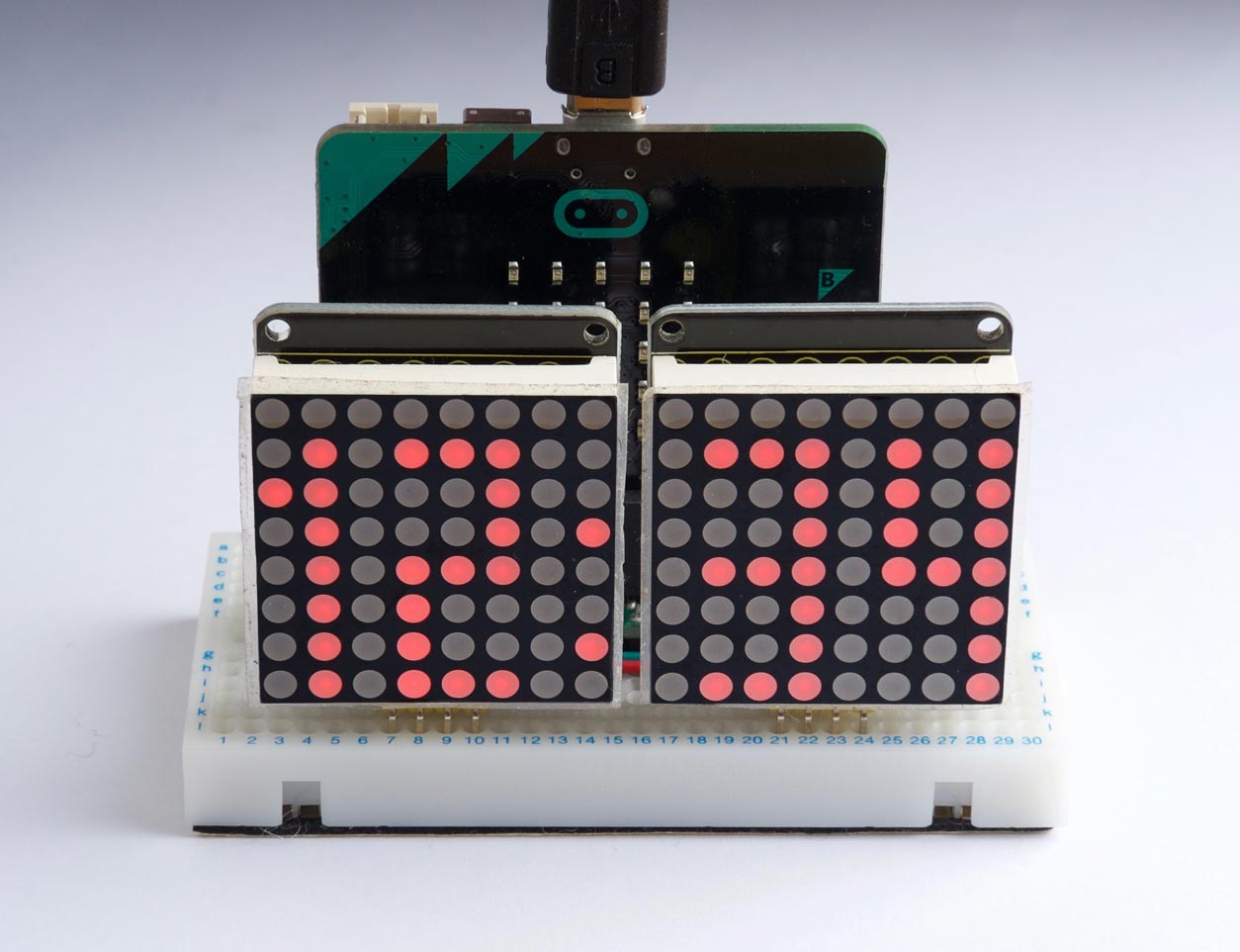
This article describes a simple 12-hour clock, written in uLisp, using two I2C dot-matrix displays to show the time:
The clock can run on any of the microcontroller boards supported by uLisp apart from the Arduino Uno, which doesn’t have quite enough memory. In the prototype I used a BBC Micro:bit.
The time is displayed on two 8x8 dot matrix LED displays, using characters based on a 3x8 matrix, and there’s even space left for a colon between the hours and minutes. I used Keyestudio I2C displays, which incorporate a HT16K33 driver chip to handle the display multiplexing and I2C interface allowing you to control them with just two I/O lines: Useful Keyestudio I2C 8x8 LED Matrix. Adafruit make a similar display: Mini 8x8 LED Matrix w/I2C Backpack. The displays include pullup resistors on SCL and SDA, so you don’t need to provide these.
Three solder links allow you to choose one of eight I2C addresses for each display, allowing you to drive up to eight displays simultaneously. You can choose an address from 0x70 (112) to 0x77 (119), and the default I2C address with no links is #x70 or 112. So, for example, you could extend this project to display the time in London and New York on two pairs of displays.
The program
First we define the character definitions for the 3x8 digits, 0 to 9:
(defvar *digits*
  '((#x7F #x41 #x7F) (#x00 #x20 #x7F) (#x4F #x49 #x79) (#x49 #x49 #x7F) (#x78 #x08 #x7F)
    (#x79 #x49 #x4F) (#x7F #x49 #x4F) (#x40 #x40 #x7F) (#x7F #x49 #x7F) (#x79 #x49 #x7F)))
The variables adr1 and adr2 are used to define the addresses of the two displays:
(defvar adr2 112)
(defvar adr1 113)
The setup routine configures the HT16K33 display driver, and sets the brightness which can be from 0 to 15:
(defun setup (addr bri)
  (with-i2c (s addr)
    (write-byte #x21 s)
    (restart-i2c s)
    (write-byte #x81 s)
    (restart-i2c s)
    (write-byte (+ #xe0 bri) s)))
The routine put writes a list of bit patterns to successive columns of a display:
(defun put (addr byt)
  (with-i2c (s addr)
    (write-byte 0 s)
    (dolist (item byt)
      (write-byte (logior (ash item -1) (ash item 7)) s)
      (write-byte 0 s))))
so, for example, this displays a diagonal line on one of the displays:
(setup adr1 8)
(put adr1 '(#x01 #x02 #x04 #x08 #x10 #x20 #x40 #x80))
The expression:
(logior (ash col -1) (ash col 7))
compensates for the fact that for some reason the rows of these displays are numbered 7, 0, 1, 2, 3, 4, 5, 6 from bottom to top.
Finally showtime calls put to display the time, in hours and minutes, on the two displays:
(defun showtime (hours mins)
  (put adr1
       (append
        (if (zerop (truncate hours 10)) '(0 0) (cdadr *digits*))
        '(0)
        (nth (mod hours 10) *digits*)
        '(0 #x12)))
  (put adr2
       (append
        '(0)
        (nth (truncate mins 10) *digits*)
        '(0)
        (nth (mod mins 10) *digits*))))
For example, to display 12:34 evaluate:
(showtime 12 34)
The number #x12 is the code to display a colon.
Here’s the main clock routine:
(defun clock (h m s)
    (setup adr1 8)
    (setup adr2 8)
    (loop
     (for-millis (1000)
       (showtime h m)
       (incf s)
       (when (= s 60) (incf m) (setq s 0)
         (when (= m 60) (incf h) (setq m 0)
           (when (= h 13) (setq h 1)))))))
To run the clock call clock with the current time, in hours, minutes, and seconds. For example:
(clock 12 34 00)
Alternative digits
The nice thing about using dot matrix displays is that you can be creative, and customise the display digits to suit your preferences. For example, here are some alternative character definitions for rounded digits:
(defvar *digits*
  '((#x3E #x41 #x3E) (#x00 #x20 #x7F) (#x27 #x49 #x31) (#x2A #x49 #x36) (#x18 #x28 #x7F)
    (#x7A #x49 #x4E) (#x3E #x49 #x26) (#x47 #x48 #x70) (#x36 #x49 #x36) (#x30 #x48 #x3F)))

