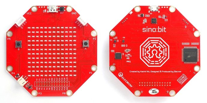
uLisp ARM Version 3.3 supports the Sino:bit, a single-board computer developed for use in Chinese schools. It is inspired by the BBC Micro:bit and Calliope mini, and shares many of their features:
The performance is the same as the BBC Micro:bit.
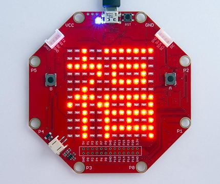
One interesting feature of the Sino:bit is its 12x12 LED matrix which you can program to display text in non-Latin characters, play games, or plot simple graphs. It might even be possible to display an analogue clock face on it. It is controlled by a Holtec HT1632C LED driver chip, simplifying the addressing and refreshing of the display.
Like the BBC Micro:bit it is based on the Nordic Semiconductor nRF51822 ARM Cortex-M0 microcontroller running at 16 MHz and with 256 Kbytes of flash program memory:
It’s available from the manufacturer Elecrow in Shenzhen, China:
It includes two push buttons, banana plug/crocodile clip connections, a JST battery connector, and Grove connectors for I2C and serial. The board also includes an NXP MMA8653FC 3-axis, 10-bit digital accelerometer and an NXP MAG3110 3-axis digital magnetometer.
USB cable
Note that the Sino:bit appears to be quite finniky about what USB cable you use, at least on the MacBook Pro I was using. When you connect the board to the USB port a drive titled MICROBIT should be mounted. This wasn’t happening, and I couldn’t upload programs from the Arduino IDE. The solution was to use a USB cable no longer than 7" or 180mm.
Installing uLisp on the Sino:bit
The procedure is the same as for the BBC Micro:bit; see Installing uLisp on the BBC Micro:bit.
Pin connections
The Sino:bit has 8 pads which can take crocodile clips or banana plugs. Six of these are labelled P0 to P5 and are connected to I/O pins 0 to 5. The other two are labelled GND and VCC (+3.3V).
The board also includes two pushbuttons.
Buttons
The Sino:bit provides two pushbuttons on pins 5 (A) and 11 (B). You can read these with the following program:
(defun buttons ()
  (pinmode 5 nil)
  (pinmode 11 nil)
  (loop
   (print
    (list (digitalread 5) (digitalread 11)))
   (delay 1000)))
Run it by typing:
(buttons)
LED matrix
The Sino:bit provides a matrix of 12 x 12 LEDs, controlled by a Holtec HT1632C LED driver chip:
Initialising the driver
The following functions allow you to send a command to the display controller, and initialise the display:
(defvar *cmd* #b100)
(defvar *write* #b101)

; Write 8-bit command
(defun command (cmd)
  (with-spi (s 16 1000 1 0)
    (write-byte (logior (ash *cmd* 5) (logand (ash cmd -3) #x1f)) s)
    (write-byte (logand (ash cmd 5) #xe0) s)))

; Initialise LEDs
(defun init ()
  ; SYS_EN, LED_ON, BLINK_OFF, RC_MASTER, COMMON_16NMOS, PWM_CONTROL = 0xf
  (mapc command '(#x01 #x03 #x08 #x18 #x24 #xa8)))
Writing to the display
The LEDs are addressed by a series of 7-bit addresses. Each address can be set to a 4-bit data value to specify the state of a column of four contiguous LEDs.
The following function write writes a 4-bit data byte to specify the state of the 4 LEDs at one address:
(defun write (ads data)
  (with-spi (s 16 1000 1 0)
     (write-byte (logior (ash *write* 5) (ash ads -2)) s)
     (write-byte (logior (logand (ash ads 6) #xc0) (ash data 2)) s)))
So to set the bottom leftmost LED you would write #x01 to address #x02:
(write #x02 #x01)
Displaying a bitmap
The following function put displays a bitmap on the display:
(defun put (&rest byt)
  (dotimes (n 12)
    (with-spi (s 16 1000 1 0)
       (let ((col (nth (- 11 n) byt))
             (ads (* n 4)))
         (write-byte (logior (ash *write* 5) (ash ads -2)) s)
         (write-byte (logior (logand (ash ads 6) #xc0) (logand (ash col -6) #x3f)) s)
         (write-byte (logior (logand (ash col 2) #xfc)) s)))))
The bitmap is specified as a series of 12 12-bit numbers. For example, the following call displays the Chinese character displayed above:
(put #b100000111111
     #b101110101010
     #b101010101010
     #b101010111110
     #b101010101010
     #b101110101010
     #b100000111111
     #b001100010000
     #b001010100000
     #b111001111111
     #b001000100000
     #b001000010000)
To design a shape to be plotted draw it on squared paper, then rotate it through 90° counter-clockwise before translating it into binary numbers. In other words, the first binary number corresponds to the rightmost column of the pattern, and so on.
Analogue inputs
The Sino:bit mini provides six 10-bit analogue inputs, on pins 0 to 4 and 10. Five of them are available on the edge connector pins labelled P0 to P4.
MMA8653FC 3-axis, 10-bit digital accelerometer
The accelerometer is on I2C address 29 (#x1D).
MAG3110 3-axis magnetometer
The magnetometer is on I2C address 14 (0x0E). For details of using it see:


