
This article describes a program written in uLisp to generate a truth table from a logic circuit. It can be used to verify that the circuit performs a specified function.
Introduction
I wrote this program to check logic circuits for use with Logic Lab, a project I designed that provides a selection of 12 logic gates that you can interconnect with patch cables to make a variety of different logic circuits, for experimenting with and learning about logic.
There are two versions of Logic Lab: the original one, Logic Lab, used an AVR microcontroller to simulate the logic, and the second one, Logic Lab 1G, was identical in appearance but used discrete “1G” CMOS logic gates to achieve the functionality:
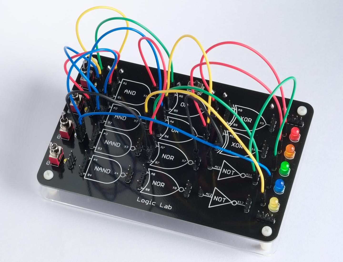
Both versions provide the same 12 logic gates: two 2-input AND, two 2-input NAND, two 2-input OR, two 2-input NOR, two 2-input XOR, and two inverters. There are four switches, S1 to S4, that can provide logic inputs to the gates, and five coloured LEDs, L1 to L5, that can display the state of the output from a gate.
A logic circuit notation
The first step was to define a Lisp-style notation for representing a logic circuit.
Each logic gate is defined as a list in the format:
(output gate input1 [input2])
In the case of the inverter there is only one input.
For example, the following circuit implements a 2-bit comparator. It compares two 2-bit binary numbers A on S1, S2 and B on S3, S4. If A and B are equal the green LED L3 lights up; otherwise the red LED L1 lights up:
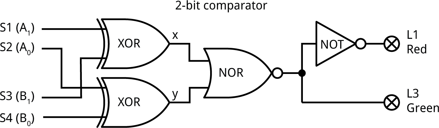
This would be represented in the Lisp-like notation as:
((x ?xor S1 S3) (y ?xor S2 S4) (L3 ?nor x y) (L1 ?not L3))
where x and y are arbitrary labels for the interconnections between gates.
Defining the gates
The first step is to define the 2-input logic gates provided in Logic Lab as Lisp functions:
(defun ?and (a b)
  (logand a b))

(defun ?nand (a b)
  (?not (logand a b)))

(defun ?or (a b)
  (logior a b))

(defun ?nor (a b)
  (?not (logior a b)))

(defun ?xor (a b)
  (logxor a b))

(defun ?xnor (a b)
  (?not (logxor a b)))

(defun ?not (a)
  (logxor a #xffff))
The names are prefixed with ‘?’ to avoid conflicts with built-in functions such as and and or.
Calculating the nodes
The following program calculates the truth table for each node in the circuit. The truth table will be represented as a 16-bit number, where bit 0 corresponds to the switch positions (0 0 0 0), bit 1 corresponds to the switch positions (0 0 0 1), and so on. We’ll format these numbers as a more conventional truth table at a later stage.
First the function switches calculates the truth-table numbers for the four switches S1 to S4:
(defun switches ()
  (let ((result (mapcar #'(lambda (x) (cons x 0)) '(S1 S2 S3 S4))))
    (dotimes (i 16)
      (dotimes (s 4)
        (incf (cdr (nth s result)) (ash (logand (ash i (- s 3)) 1) i))))
    result))
Here’s the output:
> (switches)
((s1 . 65280) (s2 . 61680) (s3 . 52428) (s4 . 43690))
where, for example, 65280 is #b1111111100000000.
The function nodes calculates the truth-table numbers for each node in the circuit from the circuit definition supplied as a parameter:
(defun nodes (circuit)
  (let ((result (append (switches) (mapcar #'(lambda (x) (cons (car x) 0)) circuit))))
    (mapc
     #'(lambda (gate)
         (let ((output (first gate))
               (fun (second gate))
               (inputs (cddr gate)))
           (let* ((args (mapcar #'(lambda (x) (cdr (assoc x result))) inputs))
                  (val (apply fun args)))
             (setf (cdr (assoc output result)) val))))
     circuit)
    result))
Here is the result with the above circuit:
> (nodes '((x ?xor S1 S3) (y ?xor S2 S4) (L3 ?nor x y) (L1 ?not L3)))
((s1 . 65280) (s2 . 61680) (s3 . 52428) (s4 . 43690)
 (x . 13260) (y . 23130) (l3 . 33825) (l1 . 31710))
Printing a truth table
Finally the following function print-truth-table prints a truth table showing the 16 possible switch positions, and the corresponding state of each node in the circuit:
(defun print-truth-table (circuit)
  (let ((values (nodes circuit)))
    (format t "(~{~2d ~}) (~{~2d ~})~%"
            (mapcar #'car (subseq values 0 4))
            (mapcar #'car (subseq values 4)))
    (dotimes (bit 16)
      (format t "(~{~2d ~}) (~{~2d ~})~%"
              (mapcar #'(lambda (x) (logand (ash (cdr x) (- bit)) 1))
                      (subseq values 0 4))
              (mapcar #'(lambda (x) (logand (ash (cdr x) (- bit)) 1))
                      (subseq values 4))))
    nil))
Here’s the result for this circuit:
>  (print-truth-table '((x ?xor S1 S3) (y ?xor S2 S4) (L3 ?nor x y) (L1 ?not L3)))
(s1 s2 s3 s4 ) ( x  y l3 l1 )
( 0  0  0  0 ) ( 0  0  1  0 )
( 0  0  0  1 ) ( 0  1  0  1 )
( 0  0  1  0 ) ( 1  0  0  1 )
( 0  0  1  1 ) ( 1  1  0  1 )
( 0  1  0  0 ) ( 0  1  0  1 )
( 0  1  0  1 ) ( 0  0  1  0 )
( 0  1  1  0 ) ( 1  1  0  1 )
( 0  1  1  1 ) ( 1  0  0  1 )
( 1  0  0  0 ) ( 1  0  0  1 )
( 1  0  0  1 ) ( 1  1  0  1 )
( 1  0  1  0 ) ( 0  0  1  0 )
( 1  0  1  1 ) ( 0  1  0  1 )
( 1  1  0  0 ) ( 1  1  0  1 )
( 1  1  0  1 ) ( 1  0  0  1 )
( 1  1  1  0 ) ( 0  1  0  1 )
( 1  1  1  1 ) ( 0  0  1  0 )
nil
From this we can confirm that the light L3 is lit when (S1, S2) and (S3, S4) are equal, and L1 is lit otherwise, so the logic circuit achieves the required functionality.